Data Center Architecture Overview
-
The data center is home to the computational power, storage, and applications necessary to support an enterprise business.
The data center infrastructure is central to the IT architecture, from which all content is sourced or passes through. Proper planning of the data center infrastructure design is critical, and performance, resiliency, and scalability need to be carefully considered.
Another important aspect of the data center design is flexibility in quickly deploying and supporting new services. Designing a flexible architecture that has the ability to support new applications in a short time frame can result in a significant competitive advantage. Such a design requires solid initial planning and thoughtful consideration in the areas of port density, access layer uplink bandwidth, true server capacity, and oversubscription, to name just a few.The data center network design is based on a proven layered approach, which has been tested and improved over the past several years in some of the largest data center implementations in the world. The layered approach is the basic foundation of the data center design that seeks to improve scalability, performance, flexibility, resiliency, and maintenance. Figure 1-1 shows the basic layered design.
Figure 1-1 Basic Layered Design
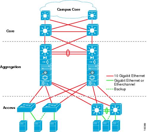
The layers of the data center design are the core, aggregation, and access layers. These layers are referred to extensively throughout this guide and are briefly described as follows:
- Core layer—Provides the high-speed packet switching backplane for all flows going in and out of the data center. The core layer provides connectivity to multiple aggregation modules and provides a resilient Layer 3 routed fabric with no single point of failure. The core layer runs an interior routing protocol, such as OSPF or EIGRP, and load balances traffic between the campus core and aggregation layers using Cisco Express Forwarding-based hashing algorithms.
- Aggregation layer modules—Provide important functions, such as service module integration, Layer 2 domain definitions, spanning tree processing, and default gateway redundancy. Server-to-server multi-tier traffic flows through the aggregation layer and can use services, such as firewall and server load balancing, to optimize and secure applications. The smaller icons within the aggregation layer switch in Figure 1-1 represent the integrated service modules. These modules provide services, such as content switching, firewall, SSL offload, intrusion detection, network analysis, and more.
- Access layer—Where the servers physically attach to the network. The server components consist of 1RU servers, blade servers with integral switches, blade servers with pass-through cabling, clustered servers, and mainframes with OSA adapters. The access layer network infrastructure consists of modular switches, fixed configuration 1 or 2RU switches, and integral blade server switches. Switches provide both Layer 2 and Layer 3 topologies, fulfilling the various server broadcast domain or administrative requirements.
This chapter defines the framework on which the recommended data center architecture is based and introduces the primary data center design models: the multi-tier and server cluster models.
Data Center Design Models
The multi-tier model is the most common design in the enterprise. It is based on the web, application, and database layered design supporting commerce and enterprise business ERP and CRM solutions. This type of design supports many web service architectures, such as those based on Microsoft .NET or Java 2 Enterprise Edition. These web service application environments are used by ERP and CRM solutions from Siebel and Oracle, to name a few. The multi-tier model relies on security and application optimization services to be provided in the network.
The server cluster model has grown out of the university and scientific community to emerge across enterprise business verticals including financial, manufacturing, and entertainment. The server cluster model is most commonly associated with high-performance computing (HPC), parallel computing, and high-throughput computing (HTC) environments, but can also be associated with grid/utility computing. These designs are typically based on customized, and sometimes proprietary, application architectures that are built to serve particular business objectives.
Chapter 2 “Data Center Multi-Tier Model Design,” provides an overview of the multi-tier model, and Chapter 3 “Server Cluster Designs with Ethernet,” provides an overview of the server cluster model. Later chapters of this guide address the design aspects of these models in greater detail.
Multi-Tier Model
The multi-tier data center model is dominated by HTTP-based applications in a multi-tier approach. The multi-tier approach includes web, application, and database tiers of servers. Today, most web-based applications are built as multi-tier applications. The multi-tier model uses software that runs as separate processes on the same machine using interprocess communication (IPC), or on different machines with communications over the network. Typically, the following three tiers are used:
- Web-server
- Application
- Database
Multi-tier server farms built with processes running on separate machines can provide improved resiliency and security. Resiliency is improved because a server can be taken out of service while the same function is still provided by another server belonging to the same application tier. Security is improved because an attacker can compromise a web server without gaining access to the application or database servers. Web and application servers can coexist on a common physical server; the database typically remains separate.
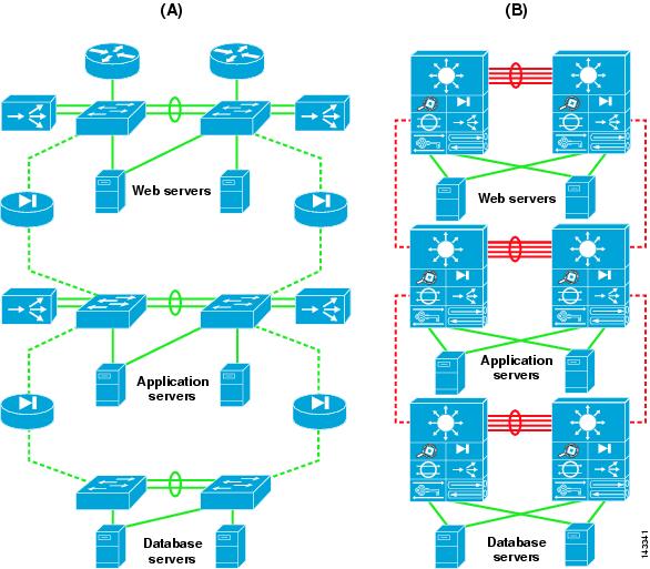
Resiliency is achieved by load balancing the network traffic between the tiers, and security is achieved by placing firewalls between the tiers. You can achieve segregation between the tiers by deploying a separate infrastructure composed of aggregation and access switches, or by using VLANs (see Figure 1-2).
Figure 1-2 Physical Segregation in a Server Farm with Appliances (A) and Service Modules (B)
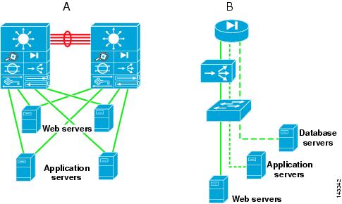
The design shown in Figure 1-3 uses VLANs to segregate the server farms. The left side of the illustration (A) shows the physical topology, and the right side (B) shows the VLAN allocation across the service modules, firewall, load balancer, and switch. The firewall and load balancer, which are VLAN-aware, enforce the VLAN segregation between the server farms. Note that not all of the VLANs require load balancing. For example, the database in the example sends traffic directly to the firewall.
Figure 1-3 Logical Segregation in a Server Farm with VLANs
Physical segregation improves performance because each tier of servers is connected to dedicated hardware. The advantage of using logical segregation with VLANs is the reduced complexity of the server farm. The choice of physical segregation or logical segregation depends on your specific network performance requirements and traffic patterns.
Business security and performance requirements can influence the security design and mechanisms used. For example, the use of wire-speed ACLs might be preferred over the use of physical firewalls. Non-intrusive security devices that provide detection and correlation, such as the Cisco Monitoring, Analysis, and Response System (MARS) combined with Route Triggered Black Holes (RTBH) and Cisco Intrusion Protection System (IPS) might meet security requirements. Cisco Guard can also be deployed as a primary defense against distributed denial of service (DDoS) attacks. For more details on security design in the data center, refer to Server Farm Security in the Business Ready Data Center Architecture v2.1 at the following URL: http://www.cisco.com/en/US/docs/solutions/Enterprise/Data_Center/ServerFarmSec_2.1/ServSecDC.html.
Server Cluster Model
In the modern data center environment, clusters of servers are used for many purposes, including high availability, load balancing, and increased computational power. This guide focuses on the high performance form of clusters, which includes many forms. All clusters have the common goal of combining multiple CPUs to appear as a unified high performance system using special software and high-speed network interconnects. Server clusters have historically been associated with university research, scientific laboratories, and military research for unique applications, such as the following:
- Meteorology (weather simulation)
- Seismology (seismic analysis)
- Military research (weapons, warfare)
Server clusters are now in the enterprise because the benefits of clustering technology are now being applied to a broader range of applications. The following applications in the enterprise are driving this requirement:
- Financial trending analysis—Real-time bond price analysis and historical trending
- Film animation—Rendering of artist multi-gigabyte files
- Manufacturing—Automotive design modeling and aerodynamics
- Search engines—Quick parallel lookup plus content insertion
In the enterprise, developers are increasingly requesting higher bandwidth and lower latency for a growing number of applications. The time-to-market implications related to these applications can result in a tremendous competitive advantage. For example, the cluster performance can directly affect getting a film to market for the holiday season or providing financial management customers with historical trending information during a market shift.
HPC Cluster Types and Interconnects
In the high performance computing landscape, various HPC cluster types exist and various interconnect technologies are used. The top 500 supercomputer list at www.top500.org provides a fairly comprehensive view of this landscape. The majority of interconnect technologies used today are based on Fast Ethernet and Gigabit Ethernet, but a growing number of specialty interconnects exist, for example including Infiniband and Myrinet. Specialty interconnects such as Infiniband have very low latency and high bandwidth switching characteristics when compared to traditional Ethernet, and leverage built-in support for Remote Direct Memory Access (RDMA). 10GE NICs have also recently emerged that introduce TCP/IP offload engines that provide similar performance to Infiniband.
The Cisco SFS line of Infiniband switches and Host Channel Adapters (HCAs) provide high performance computing solutions that meet the highest demands. For more information on Infiniband and High Performance Computing, refer to the following URL: http://www.cisco.com/en/US/products/ps6418/index.html.
The remainder of this chapter and the information in Chapter 3 “Server Cluster Designs with Ethernet” focus on large cluster designs that use Ethernet as the interconnect technology.
Although high performance clusters (HPCs) come in various types and sizes, the following categorizes three main types that exist in the enterprise environment:
- HPC type 1—Parallel message passing (also known as tightly coupled)
–Applications run on all compute nodes simultaneously in parallel.
–A master node determines input processing for each compute node.
–Can be a large or small cluster, broken down into hives (for example, 1000 servers over 20 hives) with IPC communication between compute nodes/hives.
- HPC type 2—Distributed I/O processing (for example, search engines)
–The client request is balanced across master nodes, then sprayed to compute nodes for parallel processing (typically unicast at present, with a move towards multicast).
–This type obtains the quickest response, applies content insertion (advertising), and sends to the client.
- HPC Type 3—Parallel file processing (also known as loosely coupled)
–The source data file is divided up and distributed across the compute pool for manipulation in parallel. Processed components are rejoined after completion and written to storage.
–Middleware controls the job management process (for example, platform linear file system [LFS]).
The traditional high performance computing cluster that emerged out of the university and military environments was based on the type 1 cluster. The new enterprise HPC applications are more aligned with HPC types 2 and 3, supporting the entertainment, financial, and a growing number of other vertical industries.
Figure 1-4 shows the current server cluster landscape.
Figure 1-4 Server Cluster Landscape

The following section provides a general overview of the server cluster components and their purpose, which helps in understanding the design objectives described in Chapter 3 “Server Cluster Designs with Ethernet.”
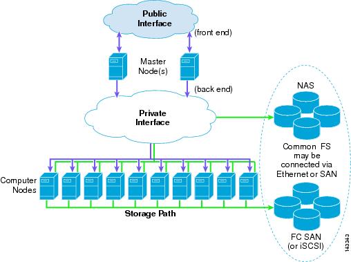
Figure 1-5 shows a logical view of a server cluster.
Figure 1-5 Logical View of a Server Cluster
Logical Overview
The components of the server cluster are as follows:
- Front end—These interfaces are used for external access to the cluster, which can be accessed by application servers or users that are submitting jobs or retrieving job results from the cluster. An example is an artist who is submitting a file for rendering or retrieving an already rendered result. This is typically an Ethernet IP interface connected into the access layer of the existing server farm infrastructure.
- Master nodes (also known as head node)—The master nodes are responsible for managing the compute nodes in the cluster and optimizing the overall compute capacity. Usually, the master node is the only node that communicates with the outside world. Clustering middleware running on the master nodes provides the tools for resource management, job scheduling, and node state monitoring of the computer nodes in the cluster. Master nodes are typically deployed in a redundant fashion and are usually a higher performing server than the compute nodes.
- Back-end high-speed fabric—This high-speed fabric is the primary medium for master node to compute node and inter-compute node communications. Typical requirements include low latency and high bandwidth and can also include jumbo frame and 10 GigE support. Gigabit Ethernet is the most popular fabric technology in use today for server cluster implementations, but other technologies show promise, particularly Infiniband.
- Compute nodes—The compute node runs an optimized or full OS kernel and is primarily responsible for CPU-intense operations such as number crunching, rendering, compiling, or other file manipulation.
- Storage path—The storage path can use Ethernet or Fibre Channel interfaces. Fibre Channel interfaces consist of 1/2/4G interfaces and usually connect into a SAN switch such as a Cisco MDS platform. The back-end high-speed fabric and storage path can also be a common transport medium when IP over Ethernet is used to access storage. Typically, this is for NFS or iSCSI protocols to a NAS or SAN gateway, such as the IPS module on a Cisco MDS platform.
- Common file system—The server cluster uses a common parallel file system that allows high performance access to all compute nodes. The file system types vary by operating system (for example, PVFS or Lustre).
Physical Overview
Server cluster designs can vary significantly from one to another, but certain items are common, such as the following:
- Commodity off the Shelf (CotS) server hardware—The majority of server cluster implementations are based on 1RU Intel- or AMD-based servers with single/dual processors. The spiraling cost of these high performing 32/64-bit low density servers has contributed to the recent enterprise adoption of cluster technology.
- GigE or 10 GigE NIC cards—The applications in a server cluster can be bandwidth intensive and have the capability to burst at a high rate when necessary. The PCI-X or PCI-Express NIC cards provide a high-speed transfer bus speed and use large amounts of memory. TCP/IP offload and RDMA technologies are also used to increase performance while reducing CPU utilization.
- Low latency hardware—Usually a primary concern of developers is related to the message-passing interface delay affecting the overall cluster/application performance. This is not always the case because some clusters are more focused on high throughput, and latency does not significantly impact the applications. The Cisco Catalyst 6500 with distributed forwarding and the Catalyst 4948-10G provide consistent latency values necessary for server cluster environments.
- Non-blocking or low-over-subscribed switch fabric—Many HPC applications are bandwidth-intensive with large quantities of data transfer and interprocess communications between compute nodes. GE attached server oversubscription ratios of 2.5:1 (500 Mbps) up to 8:1(125 Mbps) are common in large server cluster designs.
- Mesh/partial mesh connectivity—Server cluster designs usually require a mesh or partial mesh fabric to permit communication between all nodes in the cluster. This mesh fabric is used to share state, data, and other information between master-to-compute and compute-to-compute servers in the cluster.
- Jumbo frame support—Many HPC applications use large frame sizes that exceed the 1500 byte Ethernet standard. The ability to send large frames (called jumbos) that are up to 9K in size, provides advantages in the areas of server CPU overhead, transmission overhead, and file transfer time.
Figure 1-6 takes the logical cluster view and places it in a physical topology that focuses on addressing the preceding items.
Figure 1-6 Physical View of a Server Cluster Model Using ECMP
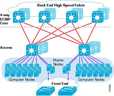
The recommended server cluster design leverages the following technical aspects or features:
- Equal cost multi-path—ECMP support for IP permits a highly effective load distribution of traffic across multiple uplinks between servers across the access layer. Although Figure 1-6 demonstrates a four-way ECMP design, this can scale to eight-way by adding additional paths.
- Distributed forwarding—By using distributed forwarding cards on interface modules, the design takes advantage of improved switching performance and lower latency.
- L3 plus L4 hashing algorithms—Distributed Cisco Express Forwarding-based load balancing permits ECMP hashing algorithms based on Layer 3 IP source-destination plus Layer 4 source-destination port, allowing a highly granular level of load distribution.
- Scalable server density—The ability to add access layer switches in a modular fashion permits a cluster to start out small and easily increase as required.
- Scalable fabric bandwidth—ECMP permits additional links to be added between the core and access layer as required, providing a flexible method of adjusting oversubscription and bandwidth per server.
In the preceding design, master nodes are distributed across multiple access layer switches to provide redundancy as well as to distribute load.
Further details on multiple server cluster topologies, hardware recommendations, and oversubscription calculations are covered in Chapter 3 “Server Cluster Designs with Ethernet.”
Tư vấn DV miễn phí
Bản tin nội bộ
- Giải pháp nào giúp tăng tốc truy cập khi sử dụng kết nối 3G?
- Người dùng Việt xem video bằng thiết bị nào nhiều nhất?
- Cảnh báo: Reset iPhone quốc tế xách tay có thể biến thành iPhone lock
- Vietnam phone codes
- Giải pháp sao lưu và khôi phục dữ liệu
- Cloud Storage
Danh mục


Tầng 2A, Số 71 Hoàng Cầu
Điện thoại: +84 4 4455 3333
E-mail: contact@econet.vn